 |
 |
 |
 |
The Forklift Laser Alignment System has become the single most effective material handling tool that addresses the issues of controlling product dame, increasing productivity, and creating a safer work environment. The laser helps guide the forklift operator for pinpoint accuracy of for tip placement. It is mounted to the forklift carriage between the forks and casts out a horizontal beam that is aligned to the tips of each fork. This mounting position allows the operator to see exactly where the forks are at all times. As the operator approaches product the beam will also shorten which allows the driver to recognize that they are close to their target. This allows the driver time for making the proper adjustments to greatly reduce the probability of the forks hitting an item they were not meant to. The Forklift Laser Alignment is a Class II laser which meets OSHA guidelines and automatically turns on at the user-prescribed height. The vertical beam is visible even at heights above 400 inches.
The return on investment with the Forklift Laser Alignment may be as fast as one week! Make your warehouse and forklift operation safer while adding to your bottom line.
Forklift Laser Alignment System Benefits
- Decrease Property Damage - Never puncture product from improper for top placement.
- Increase Productivity - The laser beam allows for proper and quicker vertical/ horizontal alignment. Quicker alignment means more pickups per day.
- Safer Work Environment - The Forklift Laser Alignment eliminates the need to search for pallet entry on high lifts. It also completely reduces the chances of pushing the product over on the backside of double racking systems.
- Lower Driver Stress & Fatigue - No more craning your neck outside the forklift to see objects or aisles. Not only is that a safety hazard but it also causes fatigue.
- Why Pay for Camera Systems - The Forklift Laser Alignment costs about 1/6 of a camera system when you include maintenance and training.
- Making Multi-Tasking Easier - The Forklift Laser Alignment provides confidence to the forklift operator of multiple types of lifting trucks. Switching from one truck to another becomes a much smoother transition.
Forklift Laser Alignment System ConfigurationsSomething important to note is that the Green Colored laser configurations appear 4 to 5 times brighter to the human eye and are much easier to see for the operator in bright conditions.
Class II Carriage Mount:
Class III Carriage Mount:
Laser Alignment System DV8R With Fork Level Memory:
Laser Alignment System Individual Parts List
Package Includes/ Components:
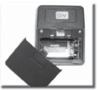
Figure 1
Magnetized mast mounted sending a unit with a 9-volt battery. Device engages Lazer Tracker beam at selected heights when battery receiving unit switch is placed in auto position (see figure 6b).
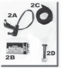
2A - Receiving unit plug placed in right side port in the receiving unit (see figure 6d) and battery port (see figure 4).
2B - 9-volt battery for sending unit.
2C - Velcro strap to secure the battery in the mounting case.
2D - Battery bracket mounting bolt and nut. Secure the battery mount shown in figure 4.
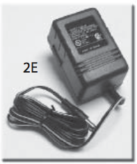
Figure 2
2E - Battery Charger
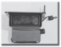
Figure 3
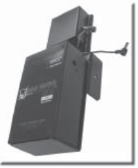
Figure 4
Laser tracker power unit (6-volt lead acid battery) and mounting case with receiving unit (forward view).
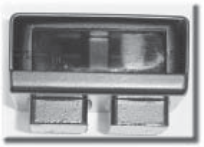
Figure 5
The bottom view magnetized mast mounted sending unit. bottom of unit points towards the battery receiving unit.
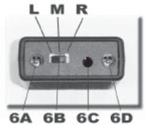
Figure 6
Bottom view battery receiving unit.
6A - Laser tracker power cord port.
6B - Unit switch (L)eft (continuous), (M)iddle (auto), or (R)ight (off). The unit must be in auto (M) position to use mounted sending unit.
6C - Fork tip leveling unit (optional).
6D - Battery port (see figure 2A).
Laser Tracker Fork Level Memory System1. When the forks are at the level the driver would like them (in most case-level), push and hold the bottom in figure 6C for approximately one (1) second, which will cause the light to disappear.
2. The signal will then be acquired and remember the level that was programmed in by holding the bottom. The level will be shown by a solid beam.
3. When the driver moves out of the acquired range within one (1) degree (approximately 3 inches), the light will flash notifying the driver that they are out of range. The light will flash slowly if it is too low or flashes quickly if it is too high.
Forklift Laser Alignment System Installation
1. Installing laser Alignment System Bar: Lift forks approximately 3 feet from the floor. Mount the tracker bar on the lift. Position it as close to the center of the carriage as possible. Be certain to position cleat at bottom of laser tracker snugly undercarriage. Finger tighten two bolts at top of the bar until the bottom of bolts reach carriage. Once laser tracker is aligned properly, tighten bolts with Allen wrench and complete by tightening lock nuts (see figure A through C).
2. Mounting Receiver and Battery Bracket: Hold bracket to forklift backrest. Position on the right side as shown in figure I. Make certain that the battery mount has adequate clearance when the carriage is side shifted.
3. Mark frame where 1/4" hole in the bracket is located. Make sure the bracket is mounted so that the receiving unit completely obscured by the bracket. Drill through the frame using a 1/4" drill bit (BLU-MOL Cobalt drill bit recommended). Mount bracket as shown in figures E through G. Place power cords through tie downs provided on battery bracket.
4. Insertion of Laser Alignment System Power Cord: Place cord behind backrest and insert into tracker port in receiving unit (see figure 6A parts description) make sure 4" cord is connected between the battery and battery port as shown in figures 2A and 4.
5. Align The Laser Light: To align the laser light insert Allen wrench (provided) into the port located below laser light. Turning wrench clockwise will lower beam. Once the beam is positioned at the desired level no further adjustments will be necessary.
6. Position The Magnetized Sending Unit on The Mast: Place a 9-volt battery into the inframe sending unit (see figure 1 in parts). Place the sending unit into magnetized metal holder and place on the mast at the desired height (see figure H). Note: the window sending unit must point down towards the battery receiving unit. The receiving unit must be set in auto (middle position) to allow the sending unit to function (see figure 6B in parts). The sending unit can be moved up or down on the mast to allow light to engage at various heights. If the operator wishes the laser to remain engaged at all times, receiving unit should be set in the continuous position (R)ight position.
7. Check The Laser Alignment Systems Bar Clearance: The laser alignment systems bar must be at least 3/4" from the floor. If no clearance is available the laser should not be used until the chain lift is properly adjusted
8. Test The Unit and Make Sure All Power Cords are Secured. Use tie-downs to secure the cords where appropriate.
Hard Wire Instructions:
1. If you are going to be operating off of the hardware system, rather than the battery operation, plug in the power cord to port shown in Figure 6D.
2. The power cord has two wires, one with a wire strip which is the positive connection.
3. Attach the wire with the grey or white stripe to the forklifts power source (optimal being 36V).
4. The other wire is the minus connection.
Maintenance Tips:
1. At the start of each shift, the new driver should check the alignment of the laser light and adjust if necessary.
2. When the battery receiving unit is in (M)iddle position if the light fails to shut off when forks are lowered, sending unit battery must be replaced (see figure 1).
3. If the light fails to function, recharge the battery. Remove the battery from the battery mount and plug it into the charger (see figure 2E). It is recommended that a fully charged backup battery be available to place into battery mount. 13-15 hours is needed to fully charge the 6-volt lead-acid battery.
4. Periodically check bolts at the top of the laser tracking systems shaft and tighten if necessary. Rember to pull the systems bar up snugly to the bottom of the carriage before tightening the bolts down.
Safety Precautions:
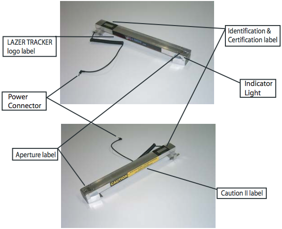
The laser product described on this webpage conforms to all applicable standards of the U.S. Department of Health and Human Services, Food and Drug Administration, Center for Devices and Radiological Health, 21CFR part 1000.
Each Forklift Laser Alignment System is Equipped With:
- Laser light emission indicator which provides a visual indication that the laser is on.
- Quick disconnect power connector to turn the laser off and totally attenuate the beam.
- Identification, certification, caution, and aperture label permanently affixed to the housing (see above diagrams).
It is the responsibility of the manufacture of the final product or system to ensure that C.D.R.H. regulations are met by the product or system. This includes ensuring that:
- No optical instruments are to be used in the path of the beam.
- No attempt is made to open the unit or modify the beam.
Operator Instructions:
Never willfully stare directly into the laser light beam. This system uses a Class II laser.
The laser alignment system uses a rechargeable battery to power the laser light. If the driver sees the light go dim and then out, or if the light does not come on at normal height, the main battery needs to be charged. Pull the plug out of the right side of the battery box. Remove the battery and connect to the charger. Replace with a charged backup battery. Insert the battery into the holder and plug in the wire from the receiving unit to the right side battery box.
At the beginning of each shift, the new driver should check the alignment of the laser light and adjust if necessary.
By moving the magnetized infrared sending unit up or down on the side of the mast, the driver can control the height at which the light will go on or off.
The laser alignment system is a high-tech industrial system, built to withstand normal everyday use. Abuse, such as slamming the forks on the floor may damage the laser light lens or diode. Respect this piece of equipment and you, as an operator, will come to realize this guidance system makes your job easier, less stressful, and more enjoyable. It is important that all persons operating a forklift equipped with a laser light reads these instructions.
Important Notes:
1. The physical copy of the operations manual must be kept on file in the office and updated upon forklift operator personnel changes.
2. These procedures are in compliance with OSHA guidelines set forth to regulate the use of Class II lasers in the workplace.
3. All forklift operators using this laser alignment system must sign an acknowledgment within the physically printed operations manual that he or she has read the instructions and has been shown how to properly use the laser alignment system and that all drivers have been informed not to willfully stare into the laser beam.

|
|
 |
 |
 |
 |
 |
 |
 |
 |
 |
 |
 |
Features
- Extremely Durable
- High-Quality Laser
- Easy and Simple Installation
|
|
 |
 |
 |
 |

|


