Home > Power Transmission > Screw Conveyors & Parts > Screw Conveyor Trough Ends

Screw Conveyor Trough Ends

The trough end portion of a screw conveyor system is essentially an endplate that supports the screw, bearing, and seal. Also commonly offered as an endplate, trough ends are responsible for withstanding a large amount of force while the screw is in operation and this force is increased as the system is longer. Our trough ends are made from high-quality heavy-gauge steel to ensure a long-term operating life and performance. Standard trough ends that house standard shaft sizes are typically in-stock and readily available but custom made trough ends can be supplied as well.

Standard Trough End Styles

Style 100 Trough Ends:

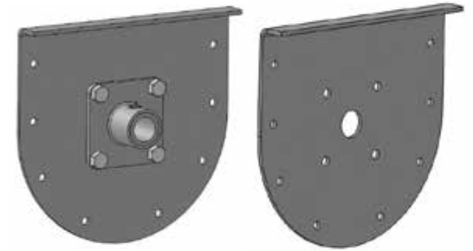
This style of trough end is a steel plate that is typically fitted with babbitted transmission flange bearings, although any bearing material may be used. The top flange supports the cover of the conveyor so this means that the system must be supported either from above or a foot on the trough end flange.
Style 101 Trough Ends:

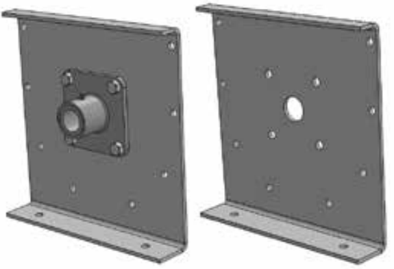
Style 101 trough ends are also a steel plate that is typically fitted with babbitted transmission flange bearings, although any bearing material may be used. However, with this design there is a top and bottom flange, meaning the top flange supports the screw conveyor cover while the bottom flange supports the bottom of the conveyor.
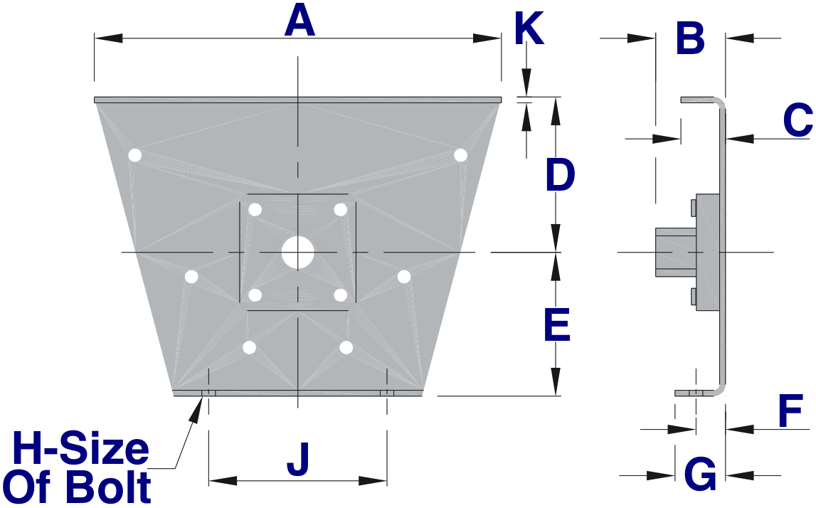
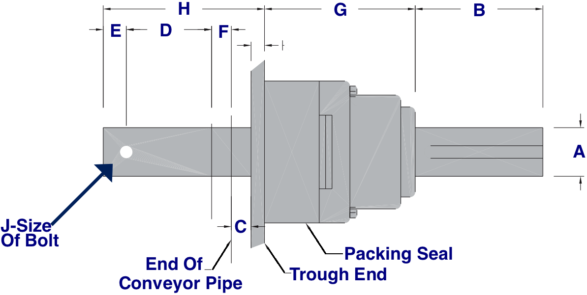
100 and 101 Trough End Dimensions

Conveyor Diameter
Bearing Bore
100 Part # With Bearing
100 Part # Without Bearing
101 Part # With Bearing
101 Part # Without Bearing
(A)
(B - With Seal)
(B Without Seal)
(C)
(D)
(E)
(F)
(G)
(H)
(J)
(K)
(L)
(M)
(N)
Weight With Bearing (LBS)
4 1 210-1400 264-1405 210-0147 264-0142 8 1 13/16 --- 1 7/16 3 5/8 4 5/8 1 1 3/8 5 3/4 3/16 3 5/16 1 1/8 7/16 8
6 1 1/2 210-1475 264-1470 210-0212 264-0217 9 3/4 3 3/16 4 15/16 1 1/2 4 1/2 5 5/8 1 1 3/8 8 1/8 3/16 4 1 1/4 7/16 13
9 1 1/2 210-1541 264-1546 210-0287 264-0282 13 1/2 3 1/4 5 1 5/8 6 1/8 7 7/8 1 1/2 1 1/2 1/2 9 3/8 1/4 4 1 1/4 7/16 23
9 2 210-1616 264-1611 210-0352 264-0357 13 1/2 4 1/4 6 1 5/8 6/18 7 7/8 1 1/2 1 1/2 1/2 9 3/8 1/4 5 1/8 1 5/8 9/16 29
10 1 1/2 210-1681 264-1686 210-0428 264-0423 14 1/2 3 1/4 5 1 3/4 6 3/8 8 7/8 1 3/4 1 3/4 1/2 9 1/2 1/4 4 1 1/4 7/16 26
10 2 210-1756 264-1827 210-0493 264-0498 14 1/2 4 1/4 6 1 3/4 6 3/8 8 7/8 1 3/4 1 3/4 1/2 9 1/2 1/4 5 5/18 1 5/8 9/16 32
12 2 210-1822 264-1892 210-0568 264-0563 17 1/4 4 1/4 6 2 7 3/4 9 5/8 1 5/8 1 5/8 5/8 12 1/4 1/4 5 5/18 1 5/8 9/16 39
12 2 7/16 210-1897 264-1967 210-0634 264-0639 17 1/4 5 1/4 7 2 7 3/4 9 5/8 1 5/8 1 5/8 5/8 12 1/4 1/4 5 5/18 1 5/8 9/16 50
12 3 210-1962 264-2106 210-0709 264-0704 17 1/4 6 1/4 8 2 7 3/4 9 5/8 1 5/8 1 5/8 5/8 12 1/4 1/4 6 2 3/4 64
14 2 7/16 210-2036 264-2171 210-0774 264-0779 19 1/4 5 5/16 7 1/16 2 9 1/4 10 7/8 1 5/8 1 5/8 5/8 13 1/2 5/16 5 5/18 1 5/8 9/16 65
14 3 210-2101 264-2312 210-0840 264-0845 19 1/4 6 5/16 8 1/16 2 9 1/4 10 7/8 1 5/8 1 5/8 5/8 13 1/2 5/16 6 2 3/4 79
16 3 210-2176 264-2387 210-0915 264-0910 21 1/4 6 5/16 8 1/16 2 1/2 10 5/8 12 2 2 5/8 14 7/8 5/16 6 2 3/4 90
18 3 210-2242 264-2452 210-0980 264-0985 24 1/4 6 3/8 8 1/8 2 1/2 12 1/8 13 3/8 2 2 5/8 16 3/8 6 2 3/4 117
18 3 7/16 210-2317 264-2528 210-1053 264-1058 24 1/4 7 3/8 9 5/8 2 1/2 12 1/8 13 3/8 2 2 5/8 16 3/8 6 3/4 2 3/4 135
20 3 210-2382 264-2593 210-1129 264-1124 26 1/4 6 3/8 8 1/8 2 1/2 13 1/2 15 2 1/4 2 1/4 3/4 19 1/4 3/8 6 2 3/4 133
20 3 7/16 210-2457 264-2668 210-1194 264-1199 26 1/4 7 3/8 9 5/8 2 1/2 13 1/2 15 2 1/4 2 1/4 3/4 19 1/4 3/8 6 3/4 2 3/4 150
24 3 7/16 210-2523 264-2734 210-1269 264-1264 30 1/4 7 3/8 9 5/8 2 1/2 16 1/2 18 1/8 2 1/2 2 1/2 3/4 20 3/8 6 3/4 2 3/4 187
Style 102 Trough Ends:

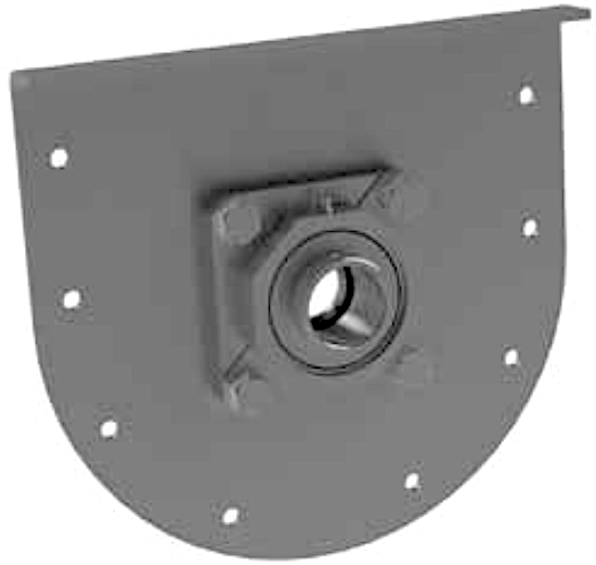
Style 102 trough ends are considered anti-friction type because it is equipped with self-aligning ball bearings, which also allows for several degrees of end shaft misalignment. This style is not recommended for use with the drive shaft unless it is for very light-duty applications, drive shafts are usually recommended to be equipped with Chevron end thrusts or another type of rigid bearing support bearing type. The top flange supports the cover of the conveyor so this means that the system must be supported either from above or a foot on the trough end flange.

Style 103 Trough Ends:


Style 103 trough ends are also considered anti-friction type because it is equipped with self-aligning ball bearings, which also allows for several degrees of end shaft misalignment. This style is not recommended for use with the drive shaft unless it is for very light-duty applications, drive shafts are usually recommended to be equipped with Chevron end thrusts or another type of rigid bearing support bearing type. The top flange supports the cover of the conveyor so this means that the system must be supported either from above or a foot on the trough end flange. However, with this design there is a top and bottom flange, meaning the top flange supports the screw conveyor cover while the bottom flange supports the bottom of the conveyor.

102 and 103 Trough End Dimensions


Diameter of Conveyor
Bearing Bore
Part# Without Feet
Weight (LBS)
Part# With Feet
Weight (LBS)
(B)
(C)
(D)
4 1 212-2034 6 212-0772 7 1 5/8 3/16 3 3/8
6 1 1/2 212-2109 10 212-0848 12 2 1/4 3/16 4
9 1 1/2 212-2174 18 212-0913 23 2 5/16 1/4 4 1/16
9 2 212-2240 20 212-0988 25 2 9/16 1/4 4 5/16
10 1 1/2 212-2315 20 212-1051 26 2 5/16 1/4 4 1/16
10 2 212-2380 22 212-1127 28 2 9/16 1/4 4 5/16
12 2 212-2455 27 212-1192 34 2 9/16 1/4 4 5/16
12 2 7/16 212-2521 32 212-1267 39 2 15/16 1/4 4 11/16
12 3 212-2596 41 212-1333 48 3 3/4 1/4 5 1/2
14 2 7/16 212-2661 44 212-1408 54 3 5/16 4 3/4
14 3 212-2737 53 212-1473 63 3 13/16 5/16 5 9/16
16 3 212-2802 61 212-1549 74 3 13/16 5/16 5 9/16
18 3 212-2877 85 212-1614 100 3 7/8 3/8 5 5/8
18 3 7/16 212-2943 92 212-1689 107 4 3/8 3/8 6 5/8
20 3 212-3016 97 212-1754 117 3 7/8 3/8 5 5/8
20 3 7/16 212-3081 104 212-1820 124 4 3/8 3/8 6 5/8
24 3 7/16 212-3156 127 212-1895 160 4 3/8 3/8 6 5/8
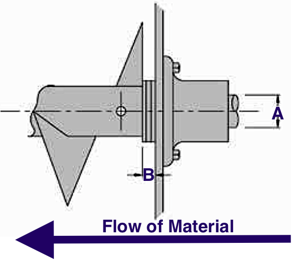
Style 104 and 107 Discharge Trough Ends:

Styles 104 and 107 trough ends are known as discharge trough ends because it is designed to be used in where the material is to flow out of the end of the trough and when the material loading does not exceed 45%. Style 104 is fitted with a self-aligning ball bearing while style 107 is typically fitted with a babbit flange bearing with the exception of two or three-bolt flanged style dependent on the shaft size. With the 104 style, shaft sizes of 1-1/2" or 2" will be fitted with a two-bolt flange and others with a three-bolt flange bearing.

104 and 107 Discharge Trough End Dimensions


Diameter of Conveyor
Bearing Bore
Style 104 Part#
Style 107 Part#
(A)
Style 104 (B)
Style 107 (B)
(C)
(D)
(K)
Weight (LBS)
6 1 1/2 220-0145 220-1408 9 3/4 2 1/4 3 3/16 1 1/2 4 1/2 3/16 9
9 1 1/2 220-0210 220-1473 13 1/2 2 5/6 3 1/4 1 5/8 6 1/8 1/4 14
9 2 220-0285 220-1549 13 1/2 2 9/6 4 1/4 1 5/8 6 1/8 1/4 16
10 1 1/2 220-0350 220-1614 14 1/2 2 5/16 3 1/4 1 3/4 6 3/8 1/4 15
10 2 220-0426 220-1689 14 1/2 2 9/16 4 1/4 1 3/4 6 3/8 1/4 17
12 2 220-0491 220-1754 17 1/4 2 9/16 4 1/4 2 7 3/4 1/4 22
12 2 7/16 220-0566 220-1820 17 1/4 2 15/16 5 1/4 2 7 3/4 1/4 27
12 3 220-0632 220-1895 17 1/4 3 3/4 6 1/4 2 7 3/4 1/4 36
14 2 7/16 220-0707 220-1960 19 1/4 3 6 5/16 2 9 1/4 5/16 32
14 3 220-0772 220-2034 19 1/4 3 13/16 6 5/16 2 9 1/4 5/16 41
16 3 220-0848 220-2109 21 1/4 3 13/16 6 5/16 2 1/2 10 5/8 5/16 50
18 3 220-0913 220-2174 24 1/4 3 7/8 6 3/8 2 1/2 12 1/8 3/8 57
18 3 7/16 220-0988 220-2240 24 1/4 4 3/8 7 3/8 2 1/2 12 1/8 3/8 66
20 3 220-1051 220-2315 26 1/4 3 7/8 6 3/8 2 1/2 13 1/2 3/8 63
20 3 7/16 220-1127 220-2380 26 1/4 4 3/8 7 3/8 2 1/2 13 1/2 3/8 70
24 3 7/16 220-1192 220-2455 30 1/4 4 3/8 7 3/8 2 1/2 16 1/2 3/8 100
Style 114 and 115 Flared Trough Ends:

Styles 114 and 115 trough ends are considered flared trough ends because of their design. Flared trough ends are formed with a top flange that supports the screw conveyor cover and a cotton flange that serves the purposes of being feet. Its design fits the contour of a flared trough and can be fitted with babbitted flange bearings as well as anti-friction self-aligning ball bearings. They can also use flange bearings of bronze, Arguto wood, Nylon, Bronze Oilite, or any other conceivable bearing material based on the application's needs. The endplate of a flared trough end can also be fitted with a Chevron or Hammond end thrust bearing.

Style 114 and 115 Dimensions


Diameter of Conveyor
Bearing Bore
Babbitt Bearing Part#
Ball Bearing Part#
(A)
Style 114 (B)
Style 115 (B)
(B)
(C)
(D)
(E)
(F)
(G)
(H)
(J)
(K)
Weight (LBS)
6 1 1/2 230-1190 230-0143 16 5/8 3 3/16 2 1/4 2 3/16 1 1/2 7 5 5/8 1 1 3/4 3/8 8 1/8 3/16 30
9 1 1/2 230-1265 230-0218 21 1/4 3 1/4 2 5/16 3 1/4 1 5/8 9 7 7/8 1 1/2 2 5/8 1/2 9 3/8 1/4 41
9 2 230-1331 230-0283 21 1/4 4 1/4 2 9/16 4 1/4 1 5/8 9 7 7/8 1 1/2 2 5/8 1/2 9 3/8 1/4 55
12 2 230-1406 230-0358 26 3/8 4 5/16 2 5/8 4 5/16 2 10 9 5/8 1 5/8 2 3/4 5/8 12 1/4 5/16 75
12 2 7/16 230-1471 230-0424 26 3/8 5 5/16 3 5 5/16 2 10 9 5/8 1 5/8 2 3/4 5/8 12 1/4 5/16 86
12 3 230-1547 230-0499 26 3/8 6 5/16 3 13/16 6 5/16 2 10 9 5/8 1 5/8 2 3/4 5/8 12 1/4 5/16 100
14 2 7/16 230-1612 230-0564 28 3/8 5 5/16 3 5 5/16 2 11 10 7/8 1 5/8 2 7/8 5/8 13 1/2 5/16 96
14 3 230-1687 230-0630 28 3/8 6 5/16 3 13/16 5 5/16 2 11 10 7/8 1 5/8 2 7/8 5/8 13 1/2 5/16 110
18 3 230-1752 230-0705 32 1/2 6 3/8 3 7/8 6 3/8 2 1/2 11 1/2 12 2 3 1/4 5/8 14 7/8 3/8 146
18 3 230-1828 230-0770 36 1/2 6 3/8 3 7/8 6 3/8 2 1/2 12 1/8 13 3/8 2 3 1/4 5/8 16 3/8 167
20 3 7/16 230-1893 230-0846 36 1/2 7 3/8 4 3/8 7 3/8 2 1/2 12 1/8 13 3/8 2 3 1/4 5/8 16 3/8 185
20 3 230-1968 230-0911 39 1/2 6 3/8 3 7/8 6 3/8 2 1/2 13 1/2 15 2 1/4 3 3/4 3/4 19 1/4 3/8 179
24 3 7/16 230-2032 230-0986 39 1/2 7 3/8 4 3/8 7 3/8 2 1/2 13 1/2 15 2 1/4 3 3/4 3/4 19 1/4 3/8 197

3 7/16 230-2107 230-1059 45 1/2 7 1/2 4 1/2 7 1/2 2 1/2 16 1/2 18 1/8 2 1/2 4 1/8 3/4 20 1/2 292
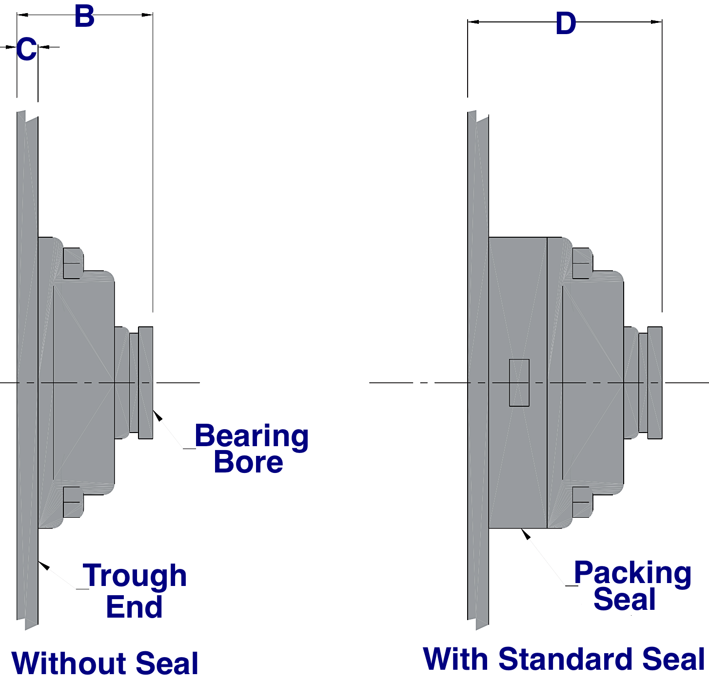
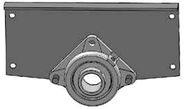
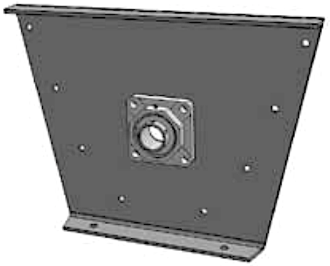
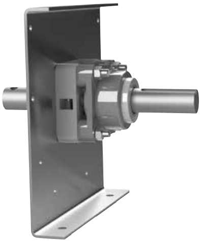
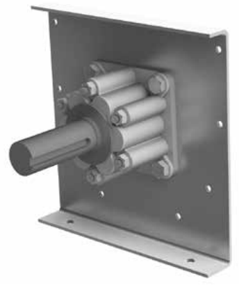
Bolt-On Shelf Trough Ends:

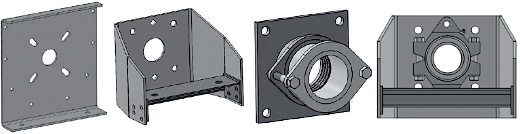
Bolt-on shelf trough ends are specially developed with bolt-on pump type seals to be adaptable to existing trough ends. This provides a cost-saving inventory reduction due to their interchangeability. The bolt-on shelf style trough ends allow for the outboard mounting of bearings which makes maintenance considerably easier. The shelf not only offers a solid mount for the bearing but provides stability for drives that include chain, v-belts, direct connect, or the use of a shaft mount reducer. The drive shaft between the bearing and seal is exposed, this makes the bearing run cooler resulting in an extended seal and bearing life. The bolt-on pump style seal is available in eight standard bore sizes and is also field adaptable on existing trough ends. This shelf offers maximum flexibility by being able to also use traditional split end seals and waste pack seals. Standardly these are made from high-quality steel but abrasion and corrosion resistant configurations can be supplied upon request.

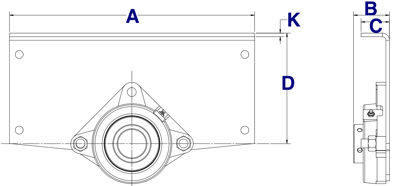
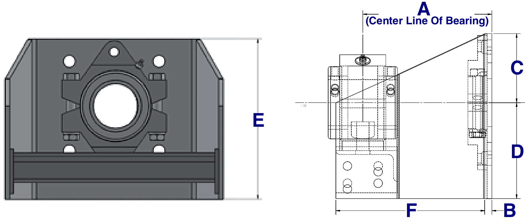
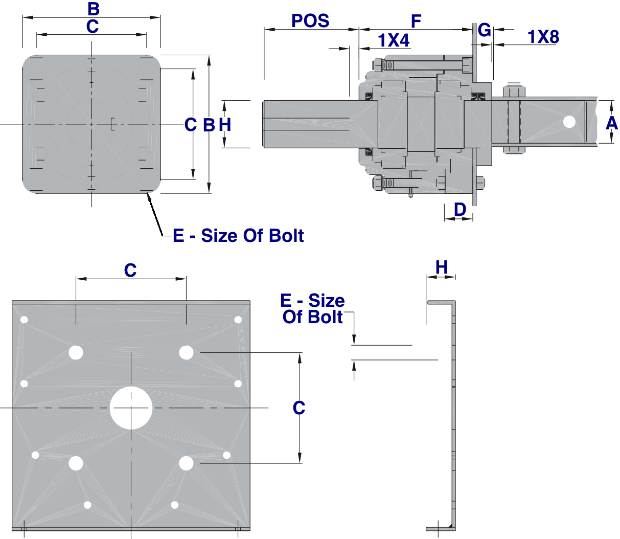
Bolt-on Shelf Dimensions


Shaft Size
Part #
(A)
(B)
(C)
(D)
(E)
(F)
Weight (LBS)
1 1/2 260-1607 8 3/16 3 4 1/2 7 1/2 9 3/16 9
2 260-1615 8 3/16 3 1/2 4 3/4 8 1/4 9 11/16 11
2 7/16 260-1623 8 1/4 1/4 4 5 1/4 9 1/4 9 3/4 17
3 260-1631 8 1/2 1/4 4 1/2 6 1/4 10 3/4 10 1/4 21
3 7/16 260-1649 8 3/4 1/4 5 1/2 6 3/4 12 1/4 10 3/4 26
3 15/16 260-1656 9 1/2 3/8 5 1/2 7 1/2 13 11 7/8 45
4 7/16 260-1664 10 3/8 6 8 1/2 14 1/2 12 3/8 54
4 15/16 260-1672 10 1/4 3/8 7 9 1/4 16 1/4 12 7/8 65
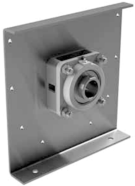
CHEVRON Roller Bearing End Thrust With Trough End:

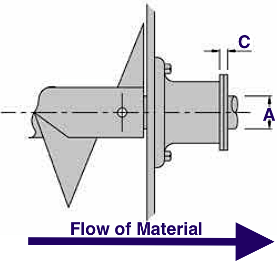
This trough end is equipped with a special roller bearing that is capable of handling medium to medium to heavy thrust and radial loads in either direction. When starting up a screw conveyor, the thrust load is created in the opposite direction of the material flow, and if the thrust load is not contained the hanger bearings, trough end, and screw all wear at an accelerated rate. The Chevron bearing assembly can be supplied with the drive or end shaft, it is always recommended that a screw conveyor is driven through this style of thrust unit rather than a self-aligning ball bearing.

CHEVRON Bearing Trough End Dimensions


Conveyor Diameter
Shaft Size (A)
(C)
(K)
#109 Part# With Drive Shaft
#109 Part# With End Shaft
Weight (LBS)
#110 Part# With Drive Shaft
#110 Part# With End Shaft
Weight (LBS)
6" 1-1/2" 1-1/16" 3/16" 242-0149 242-1337 26 240-0141 240-1339 30
9" 1-1/2" 1" 1/4" 242-0214 242-1402 35 240-0216 240-1404 40
9" 2" 1" 1/4" 242-0289 242-1477 45 240-0281 240-1479 50
10" 1-1/2" 1" 1/4" 242-0354 242-1543 37 240-0356 240-1545 43
10" 2" 1" 1/4" 242-0420 242-1618 47 240-0422 240-1610 53
12" 2" 1" 1/4" 242-0495 242-1683 52 240-0497 240-1685 60
12" 2-7/16" 1-9/16" 1/4" 242-0560 242-1758 71 240-0562 240-1750 79
12" 3" 1-5/8" 1/4" 242-0636 242-1824 97 240-0638 240-1826 105
14" 2-7/16" 1-1/2" 5/16" 242-0701 242-1899 83 240-0703 240-1891 94
14" 3" 1-9/16" 5/16" 242-0776 242-1964 109 240-0778 240-1966 120
16" 3" 1-9/16" 5/16" 242-0842 242-2038 124 240-0844 240-2030 131
18" 3" 1-1/2" 3/8" 242-0917 242-2103 133 240-0919 240-2105 158
18" 3-7/16" 2" 3/8" 242-0982 242-2178 180 240-0984 240-2170 205
20" 3" 1-1/2" 3/8" 242-1055 242-2244 161 240-1057 240-2246 174
20" 3-7/16" 2" 3/8" 242-1121 242-2319 208 240-1123 240-2311 221
24" 3-7/16" 2" 3/8" 242-1196 242-2384 240 240-1198 240-2386 257
Shaft Size
(B)
(D)
(E)
(F)
(G)
(H)
(J)
Keyset Width
Keyset Depth
Keyset Length
1-1/2" 5" 3" 7/8" 7/8" 5-1/4" 6" 1/2" 3/8" 3/16" 4-3/4"
2" 5" 3" 7/8" 7/8" 5-3/8" 6" 5/8" 1/2" 1/4" 4-3/4"
2-7/16" 5" 3" 15/16" 15/16" 5-15/16" 6-11/16" 5/8" 5/8" 5/16" 4-3/4"
3" 6" 3" 1" 1" 6-7/16" 6-7/8" 3/4" 3/4" 3/8" 5-3/4"
3-7/16" 7" 4" 1-1/4" 1-1/2" 7-1/2" 9-1/8" 7/8" 7/8" 7/16" 6-5/8"
HAMMOND Roller Bearing End Thrust With Trough End:

The Hammond bearing design is a dual tapered roller bearing end thrust that is capable of withstanding extra heavy thrust and radial loads in either direction. Although these bearings are typically mounted on steel plates you still need to specify the trough end when ordering because they are not automatically supplied.

HAMMOND Bearing Trough End Dimensions


Shaft Diameter
Drive Shaft Standard Projection
With Drive Shaft Part#
Weight (LBS)
With End Shaft Part#
Weight (LBS)
(B)
(C)
(D)
(E)
(F)
(G)
(H)
(J)
(K)
1-1/2" 4" 255-0143 60 255-0465 52 7-1/4" 5-3/4" 1-1/4" 3/4" 6-3/4" 1-3/8" 1-7/16" 4-7/8" 1-7/16"
2" 4-1/2" 255-0218 65 255-0499 56 7-1/4" 5-3/4" 1-1/4" 3/4" 6-3/4" 1-3/8" 1-15/16" 4-7/8" 1-7/8"
2-7/16" 5-1/2" 255-0283 80 255-0564 66 8" 6-1/4" 1-1/4" 7/8" 6-1/4" 1-3/8" 2-7/16" 5-5/8" 1-15/16"
3" 6" 255-0358 145 255-0630 119 10" 8" 1-3/8" 1" 8-1/4" 1-1/2" 2-15/16" 6-1/8" 2-5/16"
3-7/16" 7" 255-0424 170 255-0705 140 10" 8" 1-3/8" 1" 8-1/4" 1-1/2" 3-7/16" 6-1/8" 2-3/8"

Bronze Washer Type End Thrust

Type BW-1 Bronze Washer End Thrust:

This style is an inside style bronze washer end thrust that is mounted inside of the conveyor trough at the inlet end, it's an inexpensive assembly made to handle light to moderate compression thrust loads. The assembly consists of a transmission bronze washer flanged on each side by a machine steel washer.
Type BW-2 Bronze Washer End Thrust:

This style is mounted at the discharge end of the conveyor and is made to handle light tension thrust loads. The transmission bronze washer is held in place between the face trough end bearing hub, and a machined steel washer by a Tru-Arc thrust ring.
Shaft Size (A) Style BW-I Part # Weight Per Set (LBS) Style BW-2 Part # Weight Per Set (LBS) (B) (C) Washer Thickness
1" 275-0149 3/4 275-0560 1/2 0.75" 0.549" 1/4"
1-1/2" 275-0214 1 275-0636 3/4 0.75" 0.560" 1/4"
2" 275-0289 1-1/2 275-0701 1 0.75" 0.572" 1/4"
2-7/16" 275-0354 2-1/4 275-0776 1-1/2 0.75" 0.591" 1/4"
3" 275-0420 3 275-0842 2 0.75" 0.608" 1/4"
3-7/16" 275-0495 3 275-0917 2 0.75" 0.608" 1/4"


Sort By:
1 2 3 ... 9
   
 
1 2 3 ... 9