Jaw Couplings
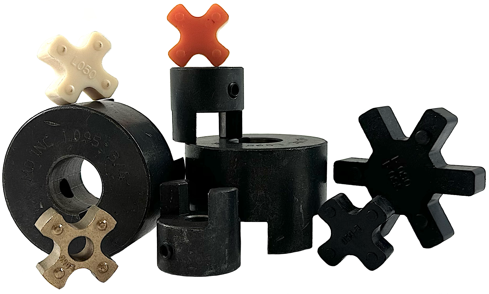
Couplings date back to the invention of the wheel; with so much history and evolution, we view couplings as more than just another power transmission component. Many things we enjoy in today's modern world would not be possible without couplings. Because of this, we pride ourselves and honor the history of couplings by supplying our clients with high-quality jaw couplings and a slew of options for insert elements (spiders). Jaw couplers have been the most widely used coupling type in power transmission industries for many years. Their highly capable and versatile yet simplistic design allows this coupling type to be utilized in various applications. Additionally, jaw couplings require no lubrication, and, in ideal circumstances, there is never metal-on-metal contact between the coupling halves (hubs), making the life of the coupling halves virtually infinite. With that being said, in situations where a catastrophic failure of the element occurs, the load will still be carried by the hubs providing a degree of failure protection. Finally, jaw couplings are resistant to oil, dirt, moisture, and grease.
Jaw couplers are composed of three basic components. Two coupling halves and one insert. Our couplings accommodate inch and metric shaft sizes from 1/2" up to 2-5/8", and torque ranges up to 6,228 inch-pounds. Depending upon the insert chosen, jaw couplers can also operate in temperatures ranging from -60°F to + 450°F.
Jaw Coupling Sizes
The chart below shows our jaw couplers' standard dimensions; please note our jaw couplings directly interchange with other brands.
|
Coupling Size
|
Type
|
Hub Dia. (A)
|
Overall Length (B)
|
Distance Between Flanges (C)
|
Length Thru Bore (D)
|
Dimension (E)
|
Dimension (HD)
|
Average Weight (LBS)
|
Set Screw Thread Size
|
Set Screw Quantity
|
| L035 |
1
|
0.625"
|
0.813"
|
0.281"
|
0.266"
|
--
|
--
|
0.10
|
#6-32UNCX1/8"
|
1
|
| L050 |
1
|
1.063"
|
1.721"
|
0.470"
|
0.625"
|
--
|
--
|
0.29
|
1/4"-20UNCX3/16"
|
1
|
| L070 |
1
|
1.375"
|
2.000"
|
0.500"
|
0.770"
|
--
|
--
|
0.56
|
1/4"-20UNCX1/4"
|
2
|
| L075 |
1
|
1.750"
|
2.126"
|
0.480"
|
0.820"
|
--
|
--
|
0.95
|
1/4"-20UNCX3/8"
|
2
|
| L090 |
1
|
2.125"
|
2.146"
|
0.490"
|
0.841"
|
--
|
--
|
1.45
|
1/4"-20UNCX3/8"
|
2
|
| L095 |
1
|
2.125"
|
2.520"
|
0.455"
|
1.020"
|
--
|
--
|
1.70
|
5/16"-18UNCX3/8"
|
2
|
| L099 |
1
|
2.531"
|
2.835"
|
0.650"
|
1.071"
|
--
|
--
|
2.50
|
5/16"-18UNCX3/8"
|
2
|
| L100 |
1
|
2.531"
|
3.459"
|
0.660"
|
1.368"
|
--
|
--
|
3.40
|
5/16"-18UNCX3/8"
|
2
|
| L110 |
1
|
3.313"
|
4.252"
|
0.843"
|
1.706"
|
--
|
--
|
6.40
|
3/8"-16UNCX5/16"
|
2
|
| L150 |
1
|
3.750"
|
4.500"
|
0.940"
|
1.771"
|
--
|
--
|
8.90
|
3/8"-16UNCX1/2"
|
2
|
| L190 |
2
|
4.500"
|
5.250"
|
0.875"
|
2.134"
|
1.340"
|
4"
|
8.75
|
1/2"-13UNCX1/2"
|
2
|
| L225 |
2
|
5.000"
|
6.142"
|
0.942"
|
2.500"
|
1.733"
|
4.25"
|
12.25"
|
1/2"-13UNCX1/2"
|
2
|
Jaw Coupling Standard Bore Sizes
The chart below shows standard bore sizes for our jaw coupling hubs (half). Please note sizes L035 - L095 are made from powdered metal, while sizes L100 - L225 are made from cast iron. Additionally,
bore sizes with * in front of them do not have a keyway; just set screws. The same bore may be available with a key-way, depending on which hub. Each bore size is a clickable link directly to the product page.
Jaw Coupling Inserts
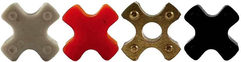
When selecting an insert for your jaw coupling, we supply options ranging in stiffness, chemical resistance, flexibility, and temperature. It is always important to note that the insert is a sacrificial component; replacement should occur when the element material is reduced by 25% (75% of the original).
- N Inserts - These inserts are made from NBR Buna synthetic rubber and are the most common element choice due to the softness of its torso and provide a high degree of flexibility with excellent resistance to oil.
- U Inserts - These inserts are made from high-quality urethane, so they are highly resistant to chemicals and provide a torque range of 150% of the type N inserts.
- H Inserts - Type H coupling inserts are made from Hytrel. This gives them the capability to operate in high-torque and high-temperature applications. They have a torque capacity of 2 to 3 times that of the N inserts, so they are common for providing higher safety factors and smaller coupling sizes.
- B Inserts - Precision made from high-quality oil-impregnated bronze, this insert provides a similar torque capacity as Hytrel while possessing excellent abrasion resistance to oils and chemicals. Bronze inserts also have the most versatile operating temperature range. The only downfall to bronze inserts is they are limited to low-speed applications.
Jaw Coupling Insert Information
The below chart summarizes the individual characteristics of the four different coupling insert options.
|
Properties
|
Buna (N)
|
Urethane (U)
|
Hytrel (H)
|
Bronze (B)
|
|
Oil Resistance
|
Good
|
Good
|
Excellent
|
Excellent
|
|
Chemical Resistance
|
Poor
|
Good
|
Excellent
|
Excellent
|
|
Flexibility
|
Excellent
|
Good
|
Fair
|
Poor
|
|
Temperature Range (Farenheight)
|
-40° to +212°
|
-30° to +160°
|
-60° to +250°
|
-40° to +450°
|
|
Temperature Range (Celsus)
|
-40° to +100°
|
-34° to +71°
|
-51° yo +121°
|
-40° to +232°
|
|
Torsional Stiffness
|
Full Soft
|
Medium Soft
|
Hard
|
Hard
|
|
Average Hardness (Shore #)
|
80A
|
90A
|
55D
|
--
|
|
Maximum Angular Misalignment
|
1°
|
1°
|
0.5°
|
0.5°
|
|
Maximum Parallel Misalignment
|
0.15"
|
0.15"
|
0.15"
|
0.10"
|
|
Insert Color
|
Black
|
Orange
|
White
|
Bronze
|
|
Insert Cost
|
Lowest
|
Moderate
|
Higher
|
Highest
|
Jaw Coupling Insert Sizes
The chart below shows our jaw insert standard dimensions; please note our jaw coupling inserts directly interchange with other brands.
|
Type N (Black) Part #
|
Weight (LBS)
|
Type H (White) Part #
|
Weight (LBS)
|
Type U (Orange) Part #
|
Weight (LBS)
|
Type B (Bronze) Part #
|
Weight (LBS)
|
| L035N |
0.01
|
--
|
--
|
--
|
--
|
--
|
--
|
| L050N |
0.01
|
L050H
|
0.01
|
L050U
|
0.01
|
L050B
|
0.01
|
| L070N |
0.01
|
L070H
|
0.04
|
L070U
|
0.01
|
L070B
|
0.01
|
| L075N |
0.01
|
L075H
|
0.04
|
L075U
|
0.02
|
L075B
|
0.02
|
| L090N |
0.01
|
L090H
|
0.04
|
L090U
|
0.02
|
L090B
|
0.02
|
| L095N |
0.01
|
L095H
|
0.04
|
L095U
|
0.02
|
L095B
|
0.02
|
| L099N |
0.01
|
L099H
|
0.06
|
L099U
|
0.02
|
L099B
|
0.02
|
| L100N |
0.01
|
L100H
|
0.06
|
L100U
|
0.02
|
L100B
|
0.02
|
| L110N |
0.16
|
L110H
|
0.20
|
L110U
|
0.20
|
L110B
|
0.20
|
| L150N |
0.30
|
L150H
|
0.30
|
L150U
|
0.30
|
L150B
|
0.30
|
| L190N |
0.40
|
L190H
|
0.40
|
L190U
|
0.40
|
L190B
|
0.40
|
| L225N |
0.40
|
L225H
|
0.40
|
L225U
|
0.40
|
L225B
|
0.40
|
|
|
This information is designed to help adequately size a jaw coupling assembly for a given application. We will provide an example for assistance with successfully running through the procedure to size a new jaw coupling application.
Example: A 10-horsepower hydraulic motor running a centrifugal pump 16 hours a day. The shaft on the motor is 1-3/8", and the pump shaft is 1-1/2". Step 1: Determine the prime mover class (see below Prime Mover Classifications Chart). - Hydraulic motors fall under Class AStep 2: Determine the load characteristics and the service factor (see the Load Characteristics and Service Factors Chart). - Centrifugal pumps are uniformly loaded. The prime mover class of the motor is A, and the motor is running over 8 hours per day; the service factor would be 1.5.Step 3: Calculate the design horsepower or design torque: ○ If Prime Mover is a 1200, 1800, or 3600 RPM motor, Design HP = Prime Mover HP X Service Factor (see the Horsepower Ratings chart & reference the corresponding motor RPM column). ○ If Prime Mover is not one of the speeds above, Design HP @ 100 RPM = (Prime Mover HP X Service Factor X 100) / Coupling RPM (see chart below and reference HP @ 100 RPM column). ○ If using Prime Mover Torque: Design HP = Prime Mover Torque X Service Factor (see below chart and reference Torque column). For the example, Prime Mover is an 1800 RPM motor. Design HP = 10 X 1.5 = 15. Looking at the Torque-Horsepower Ratings Charts, the options are L110 with Buna (type N) insert, L095 with Hytral insert (type H), or L110 with Urethane Insert (type U).Step 4: Check the Torque-Horsepower Ratings Charts for the maximum coupling bore. - 1-1/2" shaft on the pump is too late for L095 or L100 couplings. For the example, it would be best to use L100 with a Buna insert. Prime Mover Classifications:○ Class A - Electric Motors (standard duty, hydraulic motors, turbines) ○ Class B - Gasoline or steam engines (4 or more cylinders)
○ Class C - Diesel or Gas Engines, High Torque Electric Motors
Load Characteristics and Service Factors
The below chart shows typical applications and circumstances for figuring service factors.
|
Typical Applications
|
Load
|
Characteristics
|
Prime Mover Class A
|
Prime Mover Class B
|
Prime Mover Class C
|
|
Agitators (pure liquids), Blowers (centrifugal), Can and Bottle Filling Machines, Conveyors, uniformly loaded or fed (belt, chain, screw), Fans (centrifugal), Generators (uniform load), Pumps (centrifugal), Screens (air washing, water), Stokers (uniform load), Woodworking Machines (planers, routers, saws)
|
Uniform
|
Even loads - no shock - non-reversing - infrequent starts (up to 10 per day) - low starting torques
- Up to 8 hours per day
- Over 8 Hours Per Day
|
1.0
1.5
|
1.5
2.0
|
2.0
2.5
|
|
Beaters, Blowers (lobe, vane), Compressors (centrifugal, rotary), Conveyors - non-uniformly loaded or fed (belt, bucket, chain, screw), Dredge Pumps, Fans (forced draft, propeller), Kilns, Paper Mills (calendars, converting machines, conveyors, dryers, mixers, winders), Printing Presses, Pumps (gear, rotary), Shredders, Textile Machinery (dryers, dyers)
|
Moderate Shock
|
Uneven loads - moderate shock. Infrequent reversing-moderate torques
- Up to 8 hours per day
- Over 8 Hours Per Day
|
1.5
2.0
|
2.0
2.5
|
2.5
3.0
|
|
Cranes (bridge, hoist, trolly), Fans (cooling tower), Generators (welding), Hammer Mills, Mills (ball, pebble, rolling, tube, tumbling), Pumps (oil well), Wire Drawing Machines
|
Heavy Shock
|
Uneven loads - heavy shock - frequent starts and stops - high starting torques - high inertia peak loads
- Up to 8 hours per day
- Over 8 Hours Per Day
|
2.0
2.5
|
2.5
3.0
|
3.0
3.5
|
Type N Inserts Torque - Horsepower Ratings
|
Part #
|
Max. Bore
|
Max. RPM
|
Torque (IN-LBS)
|
HP Per 100 RPM
|
HP/ Speeds (1200 RPM)
|
HP/ Speeds (1800 RPM)
|
HP/ Speeds (3600 RPM)
|
|
L035
|
3/8"
|
31000
|
3.5
|
0.006
|
0.07
|
0.10
|
0.20
|
|
L050
|
5/8"
|
18000
|
26.3
|
0.042
|
0.50
|
0.75
|
1.50
|
|
L070
|
3/4"
|
14000
|
43.2
|
0.069
|
0.82
|
1.23
|
2.47
|
|
L075
|
7/8"
|
11000
|
90.0
|
0.143
|
1.71
|
2.57
|
5.14
|
|
L090
|
1"
|
9000
|
144.0
|
0.228
|
2.74
|
4.11
|
8.23
|
|
L095
|
1-1/8"
|
9000
|
194.0
|
0.308
|
3.69
|
5.54
|
11.08
|
|
L099
|
1-3/16"
|
7000
|
318.0
|
0.505
|
6.05
|
9.08
|
18.16
|
|
L100
|
1-7/16"
|
7000
|
417.0
|
0.662
|
7.94
|
11.91
|
23.82
|
|
L110
|
1-7/8"
|
5000
|
792.0
|
1.257
|
15.08
|
22.62
|
45.24
|
|
L150
|
1-7/8"
|
5000
|
1240.0
|
1.967
|
23.61
|
35.41
|
70.83
|
|
L190
|
2-1/8"
|
5000
|
1726.0
|
2.739
|
32.86
|
49.29
|
98.59
|
|
L225
|
2-5/8"
|
4600
|
2340.0
|
3.713
|
44.55
|
66.83
|
133.66
|
Type H Inserts Torque - Horsepower Ratings
|
Part #
|
Max. Bore
|
Max. RPM
|
Torque (IN-LBS)
|
HP Per 100 RPM
|
HP/ Speeds (1200 RPM)
|
HP/ Speeds (1800 RPM)
|
HP/ Speeds (3600 RPM)
|
|
L035
|
3/8"
|
31000
|
--
|
--
|
--
|
--
|
--
|
|
L050
|
5/8"
|
18000
|
50.0
|
0.079
|
0.95
|
1.43
|
2.86
|
|
L070
|
3/4"
|
14000
|
114
|
0.181
|
2.17
|
3.26
|
6.51
|
|
L075
|
7/8"
|
11000
|
227
|
0.360
|
4.32
|
6.48
|
12.97
|
|
L090
|
1"
|
9000
|
401
|
0.636
|
7.64
|
11.45
|
22.91
|
|
L095
|
1-1/8"
|
9000
|
561
|
0.890
|
10.68
|
16.02
|
32.04
|
|
L099
|
1-3/16"
|
7000
|
792
|
1.257
|
15.08
|
22.62
|
45.24
|
|
L100
|
1-7/16"
|
7000
|
1134
|
1.799
|
21.59
|
32.39
|
64.77
|
|
L110
|
1-7/8"
|
5000
|
2268
|
3.599
|
43.18
|
64.77
|
129.55
|
|
L150
|
1-7/8"
|
5000
|
3708
|
5.883
|
70.60
|
105.90
|
211.80
|
|
L190
|
2-1/8"
|
5000
|
4680
|
7.426
|
89.11
|
133.66
|
267.32
|
|
L225
|
2-5/8"
|
4600
|
6228
|
9.882
|
118.58
|
177.87
|
355.74
|
Type U Inserts Torque - Horsepower Ratings
|
Part #
|
Max. Bore
|
Max. RPM
|
Torque (IN-LBS)
|
HP Per 100 RPM
|
HP/ Speeds (1200 RPM)
|
HP/ Speeds (1800 RPM)
|
HP/ Speeds (3600 RPM)
|
|
L035
|
3/8"
|
31000
|
--
|
--
|
--
|
--
|
--
|
|
L050
|
5/8"
|
18000
|
39.4
|
0.063
|
0.75
|
1.12
|
2.25
|
|
L070
|
3/4"
|
14000
|
64.8
|
0.103
|
1.23
|
1.84
|
3.70
|
|
L075
|
7/8"
|
11000
|
135
|
0.214
|
2.56
|
3.85
|
7.71
|
|
L090
|
1"
|
9000
|
216
|
0.342
|
4.11
|
6.16
|
12.34
|
|
L095
|
1-1/8"
|
9000
|
294
|
0.462
|
5.53
|
8.31
|
16.62
|
|
L099
|
1-3/16"
|
7000
|
477
|
0.757
|
9.07
|
13.62
|
27.24
|
|
L100
|
1-7/16"
|
7000
|
626
|
0.993
|
11.91
|
17.86
|
35.73
|
|
L110
|
1-7/8"
|
5000
|
1188
|
1.885
|
22.62
|
33.93
|
67.86
|
|
L150
|
1-7/8"
|
5000
|
1860
|
2.950
|
35.41
|
53.11
|
106.24
|
|
L190
|
2-1/8"
|
5000
|
2589
|
4.108
|
49.29
|
73.93
|
147.88
|
|
L225
|
2-5/8"
|
4600
|
3510
|
5.569
|
66.82
|
100.24
|
200.49
|
Type B Inserts Torque - Horsepower Ratings
|
Part #
|
Max. Bore
|
Max. RPM
|
Torque (IN-LBS)
|
HP Per 100 RPM
|
HP/ Speeds (1200 RPM)
|
HP/ Speeds (1800 RPM)
|
HP/ Speeds (3600 RPM)
|
|
L035
|
3/8"
|
250
|
--
|
--
|
--
|
--
|
--
|
|
L050
|
5/8"
|
250
|
50.0
|
0.079
|
0.95
|
1.43
|
2.86
|
|
L070
|
3/4"
|
250
|
114
|
0.181
|
2.17
|
3.26
|
6.51
|
|
L075
|
7/8"
|
250
|
227
|
0.360
|
4.32
|
6.48
|
12.97
|
|
L090
|
1"
|
250
|
401
|
0.636
|
7.64
|
11.45
|
22.91
|
|
L095
|
1-1/8"
|
250
|
561
|
0.890
|
10.68
|
16.02
|
32.04
|
|
L099
|
1-3/16"
|
250
|
792
|
1.257
|
15.08
|
22.62
|
45.24
|
|
L100
|
1-7/16"
|
250
|
1134
|
1.799
|
21.59
|
32.39
|
64.77
|
|
L110
|
1-7/8"
|
250
|
2268
|
3.599
|
43.18
|
64.77
|
129.55
|
|
L150
|
1-7/8"
|
250
|
3708
|
5.883
|
70.60
|
105.90
|
211.80
|
|
L190
|
2-1/8"
|
250
|
4680
|
7.426
|
89.11
|
133.66
|
267.32
|
|
L225
|
2-5/8"
|
250
|
6228
|
9.882
|
118.58
|
177.87
|
355.74
|
The below charts show standard bore and key-way dimensions that comply with ANSI/ AGMA 9002-B04 Standards. These values are based on Class 1 clearance fitment.
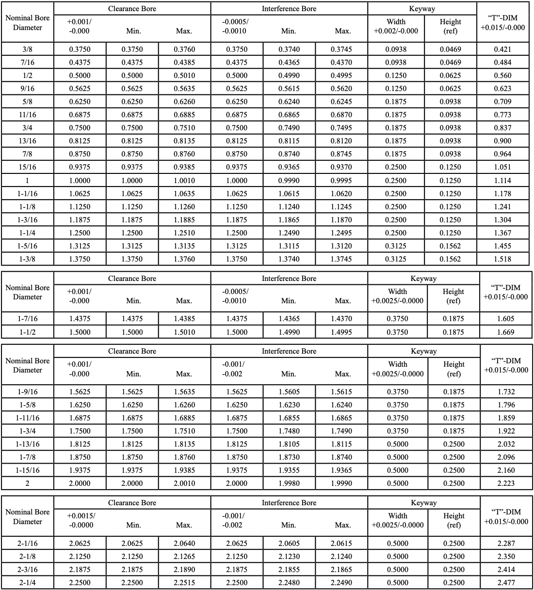 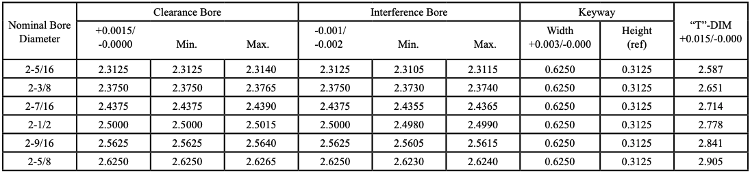 The hub key-way depth is typically one-half the standard height of the key and is measured from the side corner. The dimension from the top of the keyway to the opposite bore side (T-Dim) is calculated from the following (refer to ANSI/ AGMA 9002-B04): T = Bore + (h kw - Ch) 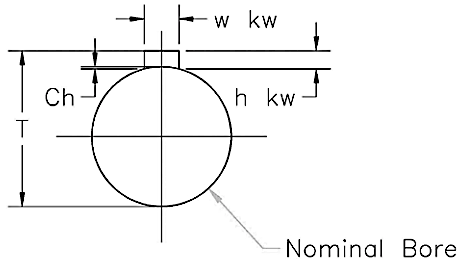 In particular circumstances, a shaft has a non-standard key and requires a step key, rectangle key, or tapered key.
The below chemical resistant chart shows the resistance to some of the most common chemicals used in power transmission applications and the resistance based on the insert material type. Please contact our customer support team for additional information if your application has a chemical not present on this chart.
Legend: A= Fluid has little to no effect | B= Fluid has minor to moderate effect | C= Fluid has severe effect | - = No data Availble
|
Chemical
|
NBR (Type N Insert)
|
Urethane (Type U Insert)
|
Hytrel (Type H Insert)
|
|
Acetone
|
C
|
C
|
B
|
|
Ammonia Anhydrous
|
-- |
-- |
-- |
|
Ammonium Hydroxide Solutions
|
C
|
C
|
A
|
|
ASTM Oil No. 1
|
A
|
A
|
A
|
|
ASTM Oil No. 3
|
A
|
B
|
A
|
|
ASTM Reference Fule A
|
A
|
A
|
A
|
|
ASTM Reference Fule B
|
A
|
B
|
A
|
|
ASTM Reference Fule C
|
B
|
C
|
B
|
|
Benzene
|
C
|
C
|
B
|
|
Butane
|
A
|
A
|
A
|
|
Carbon Tetrachloride
|
C
|
C
|
C
|
|
Chlorobenzene
|
C
|
C
|
C
|
|
Chloroform
|
C
|
C
|
C
|
|
Chromic Acid (10% - 50%)
|
C
|
C
|
-- |
|
Dowtherm A or E Solvent
|
-- |
-- |
-- |
|
Ethyl Alcohol
|
C
|
C
|
A
|
|
Ethylene Glycol
|
A
|
B
|
A
|
|
Fuel Oil
|
A
|
C
|
-- |
|
Gasoline
|
A
|
B
|
A
|
|
Glycerine
|
A
|
C |
A
|
|
Hydraulic Oils (Petroleum Based)
|
A
|
A
|
A
|
|
Hydrochloric Acid, 37% (Cold)
|
C
|
C
|
C
|
|
Hydrogen Peroxide, 90%
|
C
|
-- |
-- |
|
Isopropyl Alcohol
|
B
|
C
|
A
|
|
Kerosene
|
A
|
B
|
A
|
|
Lacquer Solvents (MEK)
|
C
|
C
|
C
|
|
Lubricating Oils
|
B
|
-- |
A |
|
Methyl Alcohol
|
C
|
C
|
A
|
|
Mineral Oil
|
A
|
A
|
A
|
|
Naphtha
|
C
|
C
|
A
|
|
Nitric Acid, 10%
|
C
|
C
|
B
|
|
Nitrobenzene
|
C
|
C
|
C
|
|
Phenol
|
C
|
C
|
B |
|
Phosphoric Acid, 20%
|
C
|
A
|
-- |
|
Phosphate Esters
|
-- |
-- |
A
|
|
Pickling Solution (20% Nitric Acid, 4% HP)
|
C
|
C
|
C
|
|
Soap Solutions
|
A
|
A
|
A
|
|
Sodium Hydroxide, 20%
|
B
|
B
|
A
|
|
Stearic Acid
|
B
|
A
|
A
|
|
Sulfuric Acid, up to 50%
|
C
|
C
|
A
|
|
Sulfuric Acid, 50% to 80%
|
C
|
C
|
C
|
|
Tannic Acid, 10%
|
A
|
-- |
A
|
|
Toluene
|
C
|
C
|
A
|
|
Trichlorentine
|
C
|
C
|
B
|
|
Water
|
A
|
-- |
B (158°) |
|
Xylene
|
C
|
C
|
B
|
|
|
|


