Roller Chain Sprocket Nomenclature
Different sprocket manufactures utilize different "terms" or nomenclature to describe their sprockets. Though, throughout the general history of roller chain sprockets almost every manufacture utilizes four different types of sprockets and has adopted the same nomenclature for them.
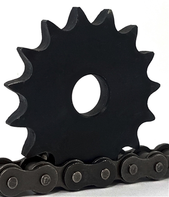
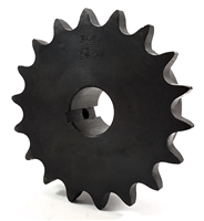
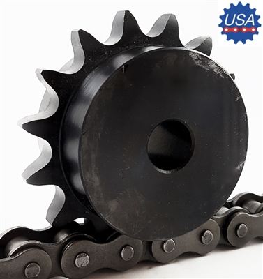
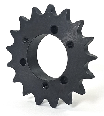
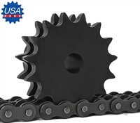
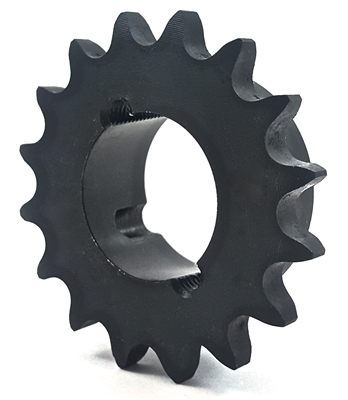
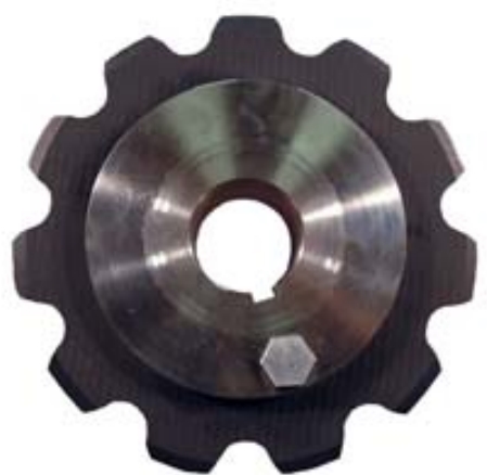
Standard Sprocket Styles
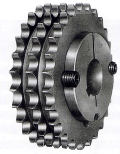
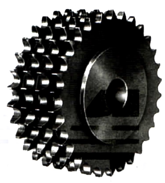
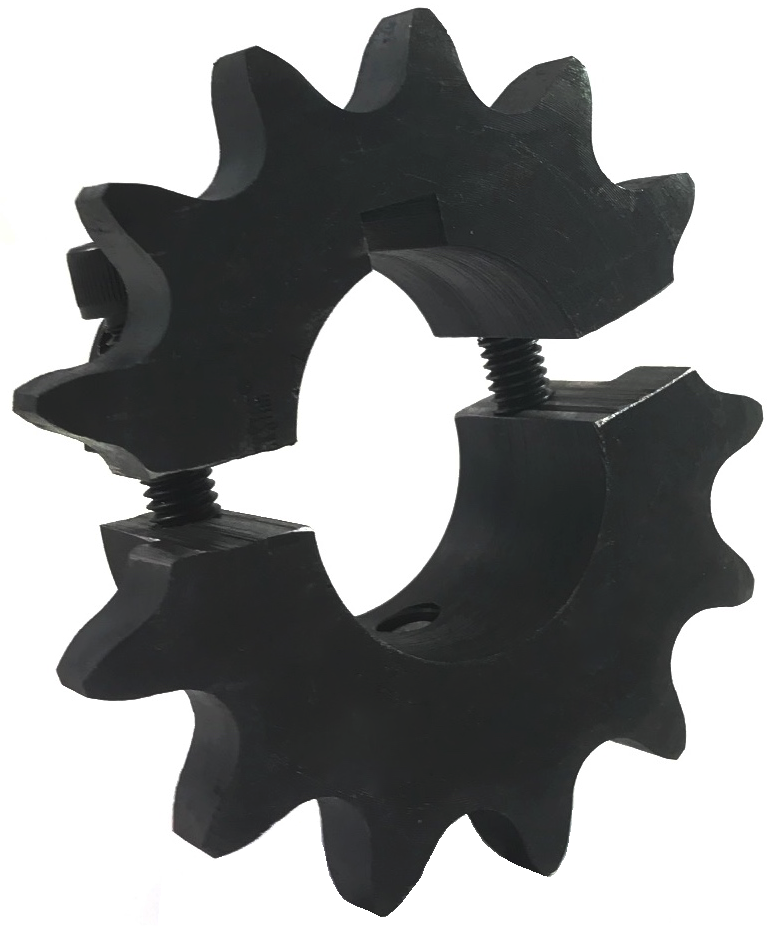
Multi-Strand Roller Chain Sprockets
Multi strand roller chain sprockets will start with a prefix except when past 4-strands. We supply single through twelve (12) strand roller chain sprockets in the four standard styles as well as various other styles upon request.
Common Sprocket Styles
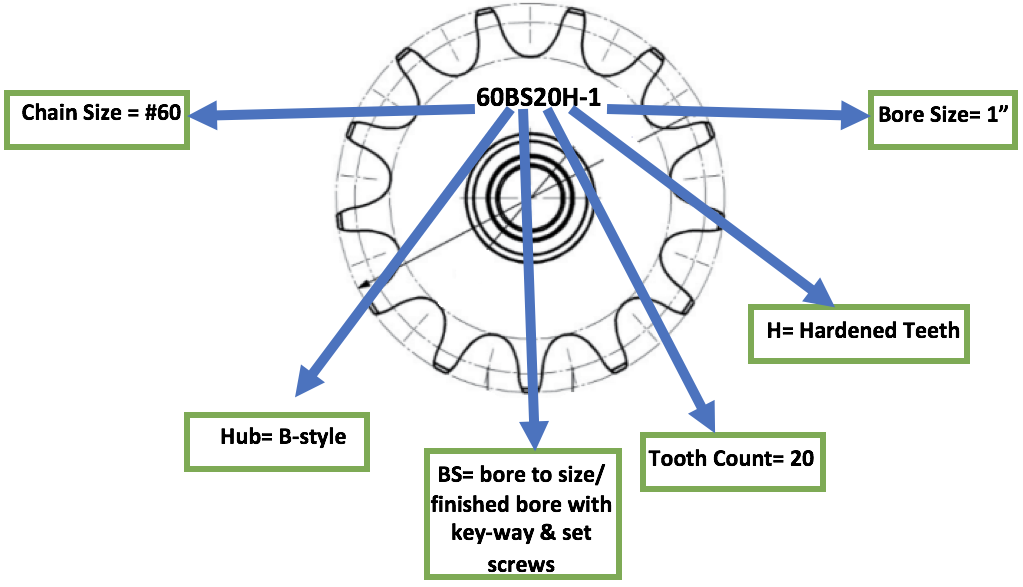
Sprocket Part Number Nomenclature
When identifying a sprocket with a part number, standardly the chain pitch will be written first, then the hub style or code, and followed by the number of teeth the sprocket has. If the sprocket is multi strand there will most often be a letter prefix at the beginning of the part number.
Behind the part number a suffix of "H" is added if the teeth are hardened from being heat-treated. If the sprocket is a QD or taper bushed style the center letter for the hub designation is changed to represent so.
Standard Sprocket With Finished Bore Example:
Some manufactures will also designate in the part number if the sprocket is manufactured from a special material. This designation can be placed in the front of the part number or behind, if it is noted.
Common Material Suffixes:
If the sprocket is a shear pin sprocket then the center hub style letter is substituted with an SP.
Sprocket Dimensional Specifications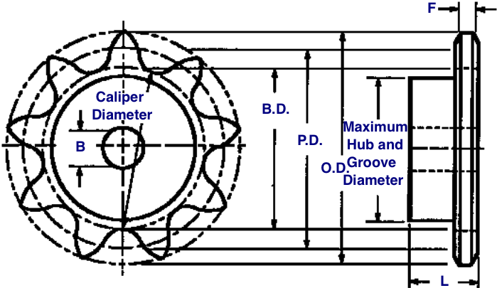
Bottom Diameter (BD) - This is the measurement of the diameter of a circle tangent to the bottoms of the tooth spaces.
Caliper Diameter - Since the bottom diameter (BD) of a sprocket with odd number of teeth cannot be measured directly, caliper diameters are the measurement across the tooth spaces nearly opposite.
Pitch Diameter (PD) - The diameter across to the pitch circle which is the circle followed by the centers of the chain pins as the sprocket revolves in mesh with the chain. PD= PITCH/ SIN(180/nT)
Outside Diameter (OD) The outside diameter is the measurement from the tip of the sprocket tooth across to the corresponding point directly across the sprocket. It is comparatively unimportant as the tooth length is not vital to proper meshing to with the chain. The outside diameter may vary depending on the type of cutter used. OD=(pitch)(0.6+COT[180/nT])
Hub Diameter (H) - Is the distance across the hub from one side to another. This diameter must not exceed the calculated diameter of the inside of the chain sidebars.
Maximum Sprocket Bore - This dimension is determined by the required hub wall thickness for proper strength. The dimensional allowance must be made for keyway and set screws.
Face Width (T) - Face width is limited in its maximum dimension to allow proper clearance to provide for chain engagement and disengagement. The minimum width is limited to provide the proper strength to carry the imposed loads.
Length Thru Bore (L) - The length thru bore must be sufficient to allow a long enough key to withstand the torque transmitted by the shaft. This also measures the stability of the sprocket on the shaft.
|
|
|